Problem
Lab 5, we experiment with feedback in a control system using an external controller. Feedback control is important since we often cannot alter the intrinsic characteristics of hardware, i.e. the DC motor used in Lab 4. In software, it is possible to simulate the response with different damping and inertial characteristics, but it is not possible to change the damping ratio or moment of inertia without assembling an entirely different motor. For this reason, it is imperative to experiment with an external controller has the ability to alter the response based on the current point in the simulation, and the intended steady state value. PID controllers do this exceptionally well, and simply adjusting the constants, P, I, and D can alter the characteristics of the response.
Procedure
Before we begin the lab it is important to understand the different system responses we may encounter. That way we know the various inputs our PID controller will face. The response we observe in the time domain is termed the transient response. There are four possible outcomes:
- Over-damped – There is lots of damping causing the system to gradually reach steady state.
- Critically Damped – There is enough damping to just stop the transient so there is no transient.
- Underdamped – The circuit has oscillation however there is damping that causes the transient to settle to steady state.
- Un-damped – The system will oscillate forever since there is no damping
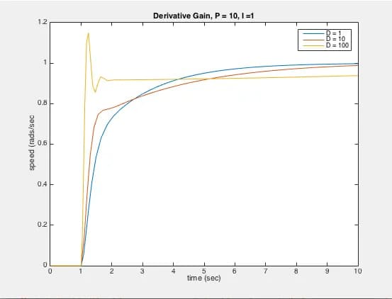
Given the various situation we may encounter what we will test is how each term in the PID controller effects our output. There are certain criteria we wish to minimize or maximize within a system’s response. For example the rise time, is the amount of time it takes the signal to go from 0.1 to 0.9 of its final value. We also care about the settling time, or the time it takes the response to stay within 2% its final value. Lastly, the percent overshoot notes the amount your signal goes over your desired final value. When designing a system it is important we know the parameters, and usage case scenarios our PID controller will operate in.
To begin we will test the effect of the P term by changing P and keeping I and D set to 0. There are four cases to test 𝑃 = 1, 10, 100, 1000. To maximize the time we have available to us in lab, we will